Shutter Timing Test Rig (DOE & Automation)
2-minute full case study (the scroll-through / deep dive)
Context & goals
Ensure the shutter meets timing spec under heat and duty-cycle variation while reducing manual effort and producing traceable, repeatable evidence for engineering sign-off.
Requirements / constraints
Target timing ± tolerance; jitter below threshold
Thermal range covering expected field conditions
Repeatable fixture; no changes to the device under test (DUT)
Automated logging with CSV export and plotted summaries
Clear pass/fail criteria and full test-matrix coverage
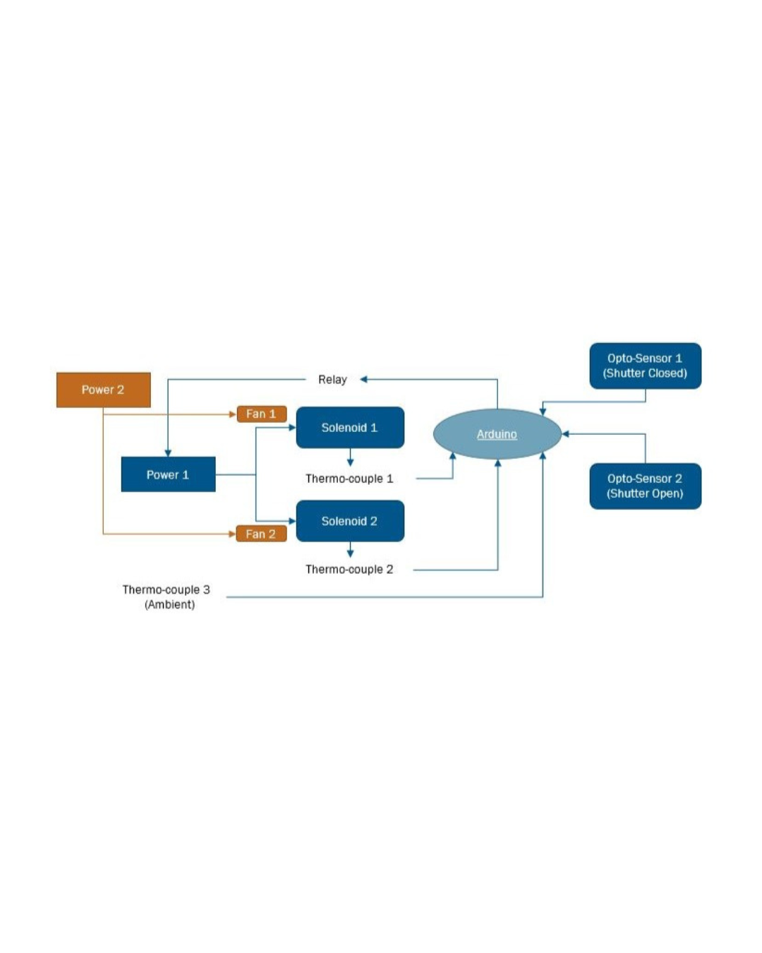
Test architecture (sanitized)
Instrumented rig: shutter + optical sensor → microcontroller (Arduino (C/C++)) with reference timing
Thermal loading: controlled heat/soak with temperature logging
Light control: shroud to block ambient light; fixed distance and angle
Fixture: rigid mount, tool-less swaps, indexing for consistent alignment
DOE plan
Factors: temperature, duty cycle, pulse width (optional: supply voltage)
Responses: actuation latency, jitter, missed events
Design: randomized order, N replicates per cell, guard runs for warm-up
Criteria: timing ≤ spec; jitter ≤ limit; 0 missed events
Automation & analysis
Acquisition: Arduino timestamps with factor levels and run IDs written to CSV
Pipeline (MATLAB): ingest → QC flags → histograms/CDFs → summary tables
Plots: latency vs. temperature; jitter distribution; control charts by factor
Results
Timing met spec across the tested thermal range; jitter below limit in all cells
Identified a duty setting that minimizes thermal drift
Generated a one-click report (plots, tables, pass/fail summary)
What I’d improve next
Add an environmental chamber with controlled ramps and humidity
Run long-duration endurance with vibration overlay
Enclose the rig; add a self-check routine and a calibration artifact
Integrate into CI for nightly regression with alerts
Gallery
-
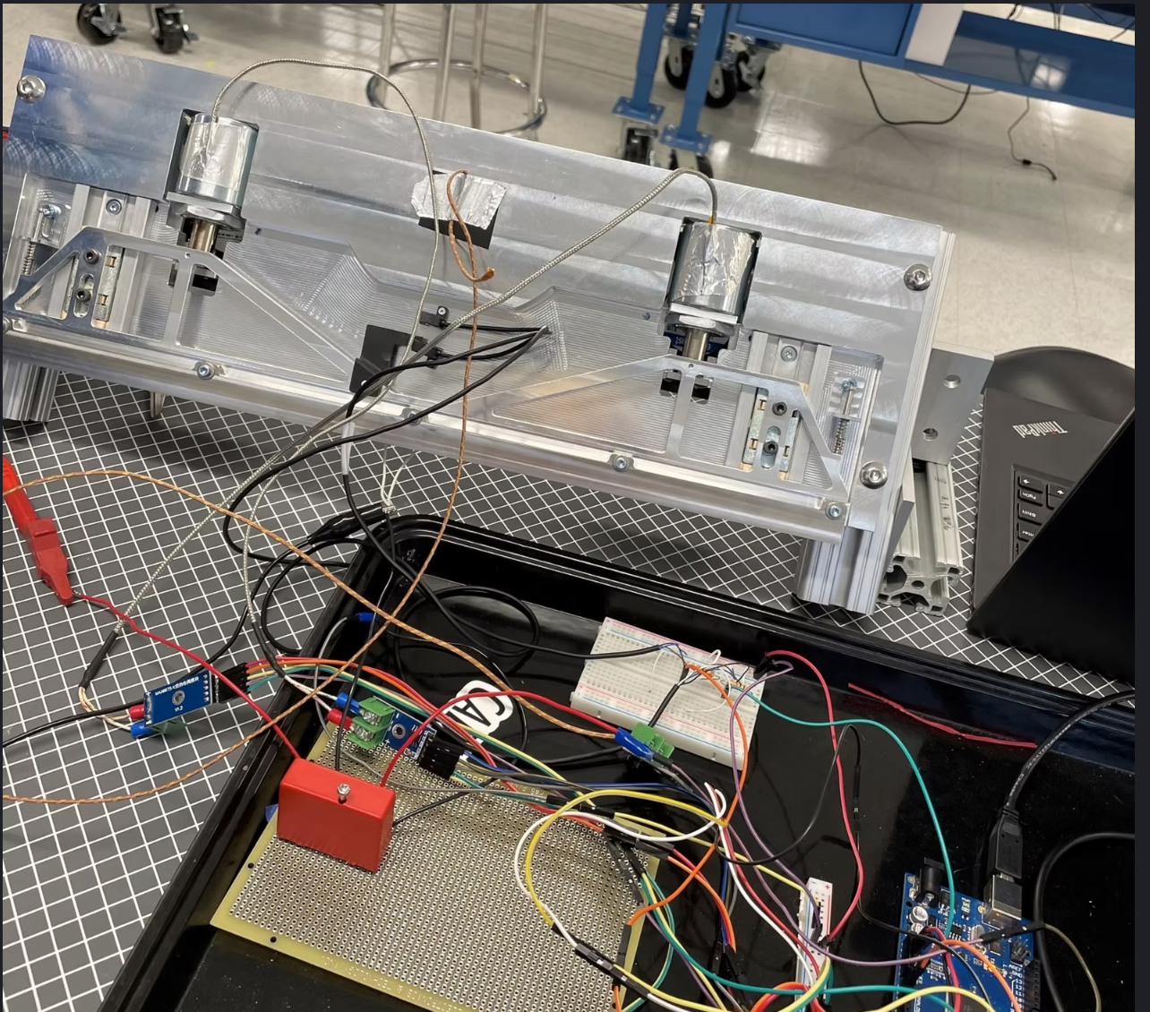
Modular bench rig with fixture, sensors, and data logging (from original DOE setup).
-
Automated cycling with MATLAB data filtering to identify key variables.
-
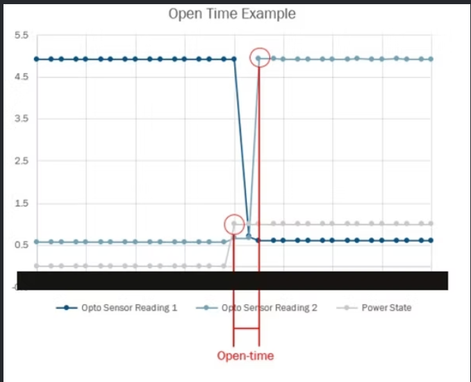
Shutter mechanism states used for timing definitions (open)
-
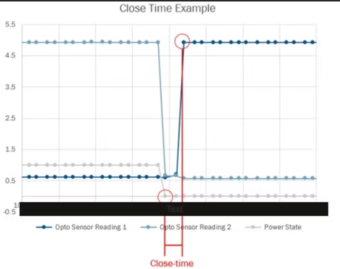
Timing definitions used for acceptance: close-time (sanitized).
-
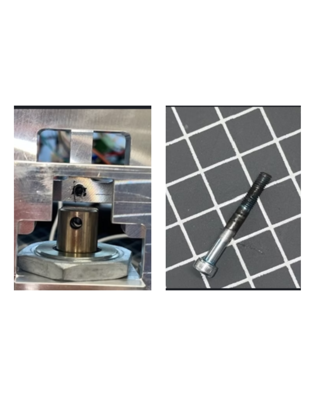
Reliability finding and corrective action: shoulder-bolt fatigue → larger shoulder bolt with pin rather than thread (no further failures observed).
-
-
-
-